1. Contact parameters:
1.1 Contact form: Pairing form of relay contacts, Table 2 gives the pairing form of a set of contact pairs, and multiple sets of contacts can be deduced by analogy.
Table 2
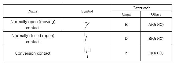
1.2 Contact resistance: refers to the total resistance between the contact resistance between the contact and the reed of the contact and the conductor resistance of the terminal. Generally expressed in mΩ.
Unless otherwise stated in the specification, a relay with a contact load of less than 1A generally measures contact resistance with 6VDC, 0.1A, and a contact with a contact load greater than 1A measures contact resistance with 6VDC, 1A.
1.3 Contact voltage drop: Generally refers to the total voltage drop across the contacts and the reeds and terminals connected to the contacts in the load circuit. Generally expressed as a voltage drop at a specified current, such as 50mV (measured at 10A).
1.4 Contact material: The material used for the contact is generally expressed in a chemical formula, such as AgNi, which is a silver-nickel alloy contact. The materials commonly used on relays, as well as their characteristics and applicable environment, can be found in Chapter 1.2 “Contact Materials” in Chapter 2, “Selection Principles for Relays”.
1.5 Contact rated load: Generally refers to the load that the contact can be reliably switched under certain specified conditions, generally expressed by a combination of voltage and current. Unless otherwise stated, the loads listed in the specification are typically resistive loads.
1.6 Maximum switching voltage: The maximum load voltage that the relay contacts can switch. Do not exceed this value during normal use, otherwise the life of the relay will decrease.
1.7 Maximum switching current: The maximum load current that can be switched by the relay contacts. Do not exceed this value during normal use, otherwise the life of the relay will decrease.
1.8 Maximum switching power: The maximum load that can be reliably switched by the relay contacts. It is generally expressed as “VA” for AC and “W” for DC.
1.9 Mechanical durability: refers to the monitoring current and voltage on the contact without applying load or voltage, and the number of times the relay can be switched normally at the specified frequency under the condition that the rated voltage is applied to the coil. "Number of times" means.
1.10 Electrical Durability: Generally refers to the specified load of a specified load ratio applied to a contact under a certain specified environmental condition. When the rated voltage is applied to the coil, the number of times the relay can be normally switched is generally expressed as “number of times”.
1.11 Inrush current: Generally refers to the instantaneous maximum current of a particular type of load that the relay contact can withstand.
1.12 Minimum applicable load: Generally refers to the reference value of the minimum load that the relay contact can switch. This reference value varies depending on the switching frequency, environmental conditions, desired contact resistance, and reliability. Therefore, perform the verification test with the actual load before use.


 selena
  sales@msrelay.com
 13968707033
 +86-577-62518811


