how to test communication relay with multimeter: a step-by-step guide
Release time:2025-09-19 20:32:21
Relays are vital components used in electrical and electronic systems to control the flow of current through a circuit. They serve as electrically operated switches, allowing low voltage signals to control high-power circuits. In communication systems, relays are frequently used to isolate different parts of the system and to ensure signals are transmitted properly. Testing these relays ensures they are functioning correctly and are not the cause of signal disruption. A multimeter, a handy tool for measuring voltage, current, and resistance, is essential for troubleshooting relays. In this article, we will explore how to test a communication relay with a multimeter, focusing on the coil, normally open (NO), and normally closed (NC) contacts.
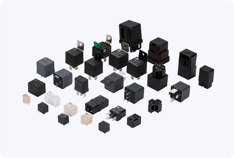
Understanding the Communication Relay Before diving into the testing process, it’s important to understand the basic structure and function of a communication relay. A typical relay consists of three main parts: Coil: The coil is an electromagnet that controls the opening or closing of the relay’s contacts. Contacts: The contacts can be of two types: Normally Open (NO) and Normally Closed (NC). The NO contacts are open when the relay is de-energized and close when it is energized. The NC contacts are closed when the relay is de-energized and open when it is energized. Armature: The armature is a movable part that gets attracted to the coil when it is energized, causing the contacts to open or close.


 Chat Oline