


Relay wiring is a fundamental aspect of electrical engineering that plays a crucial role in various applications, from industrial automation to home electronics. A relay is essentially an electrically operated switch that allows a low-power control signal to switch a high-power circuit. Understanding the principles of relay wiring is essential for anyone working with electrical systems, as it enables the safe and efficient control of electrical devices.
Relays consist of several key components: an electromagnet, an armature, a spring, and one or more sets of contacts. When an electric current flows through the electromagnet, it creates a magnetic field that pulls the armature towards it, causing the contacts to change state. This mechanism allows a small current to control a much larger current, making relays ideal for applications where high-power devices need to be controlled by low-power signals, such as microcontrollers or sensors.
The process of relay wiring begins with understanding the different types of relays available. There are several classifications based on their construction and function, including electromechanical relays, solid-state relays, and reed relays. Electromechanical relays are the most common type, using a physical switch mechanism, while solid-state relays use semiconductor devices to switch the circuit without moving parts. Reed relays, on the other hand, use magnetic reeds that close when exposed to a magnetic field.
When wiring a relay, it is essential to consider the voltage and current ratings of both the control circuit and the load circuit. The control circuit, which activates the relay, typically operates at a lower voltage (e.g., 5V or 12V), while the load circuit, which is being controlled, may operate at a higher voltage (e.g., 120V or 240V). It is crucial to ensure that the relay's contacts can handle the current and voltage of the load circuit to prevent damage or failure.
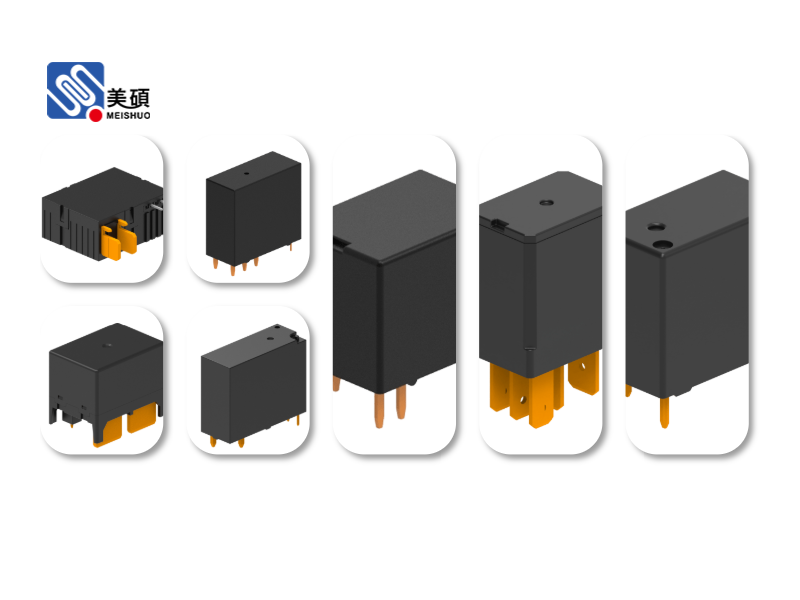
Another important aspect of relay wiring is the proper connection of the relay's pins. Most relays have at least four pins: two for the coil (control circuit) and two for the contacts (load circuit). The coil pins are usually labeled with '+' and '-' to indicate the polarity, although some relays are non-polarized. The contact pins are typically labeled as 'NO' (normally open) and 'NC' (normally closed), indicating their state when the relay is de-energized.
In addition to basic relay wiring, there are several advanced techniques that can enhance the performance and reliability of relay circuits. One such technique is the use of a flyback diode, which is connected in parallel with the relay coil. When the relay is de-energized, the coil generates a voltage spike that can damage the control circuit. The flyback diode provides a path for this current, protecting the circuit from voltage surges.
Another important consideration is the use of relay modules, which simplify the wiring process by integrating the relay with other components such as optocouplers and protection circuits. These modules are particularly useful in applications where multiple relays are needed, as they provide a compact and organized solution.
Relay wiring also involves safety considerations. Since relays are often used to control high-power circuits, it is essential to follow proper safety protocols, such as using appropriate wire gauges, insulating materials, and circuit breakers. Additionally, it is important to ensure that the relay is properly grounded to prevent electrical shocks and interference.
In conclusion, relay wiring is a critical skill for anyone working with electrical systems. By understanding the principles of relay operation, selecting the right type of relay, and following proper wiring techniques, you can create reliable and efficient circuits that meet the needs of various applications. Whether you are building a simple home automation system or a complex industrial control system, a solid understanding of relay wiring will help you achieve your goals safely and effectively.

 Chat Oline