


In the realm of electrical engineering, the relay electrical diagram plays a crucial role in the design and implementation of various circuits. This article aims to provide a comprehensive guide to understanding relay electrical diagrams, their significance, and how to read them effectively.
**Introduction**
A relay electrical diagram, also known as a relay circuit diagram, is a visual representation of a relay circuit. It provides a clear and concise depiction of the components, connections, and functions within the circuit. Relay diagrams are widely used in electrical engineering, automation, and control systems to design, troubleshoot, and maintain circuits.
**Components of a Relay Electrical Diagram**
A typical relay electrical diagram consists of the following components:
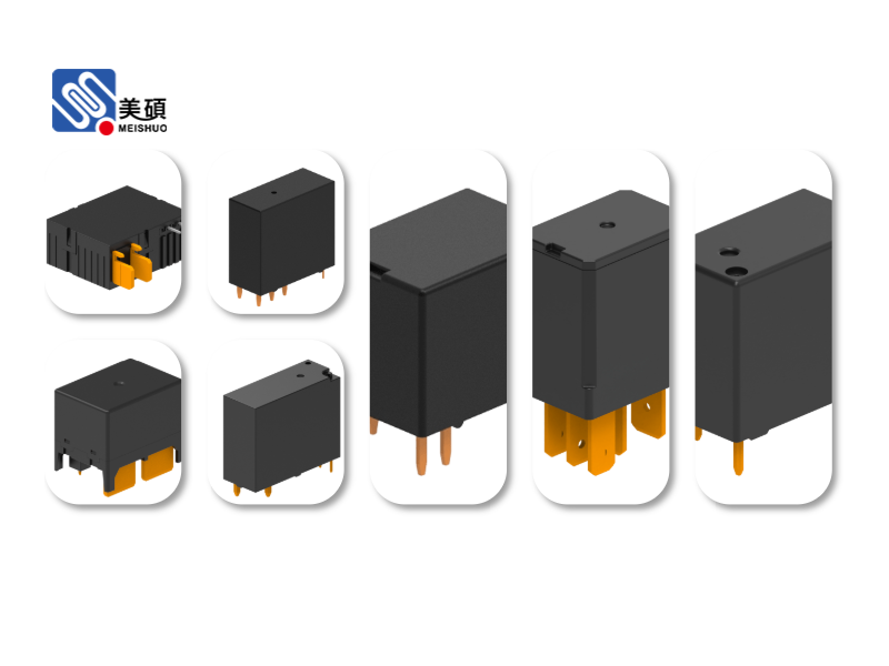
1. **Relay**: The relay is the central component of the diagram. It is an electromagnetic switch that operates on low power and controls high-power circuits. Relays are used to isolate circuits, switch high currents, and provide electrical isolation between circuits.
2. **Coil**: The coil is an electromagnet that energizes the relay. When an electrical current flows through the coil, it generates a magnetic field, which attracts the armature and closes the switch contacts.
3. **Contacts**: Contacts are the electrical connections that make or break the circuit. They are usually mounted on the armature and move as the relay operates. Contacts can be normally open (NO) or normally closed (NC), depending on their state when the relay is de-energized.
4. **Power Supply**: The power supply provides the necessary electrical energy to the relay coil. It can be AC or DC, depending on the relay's specifications.
5. **Control Circuit**: The control circuit is the circuit that controls the operation of the relay. It can include sensors, switches, and other components that provide input signals to the relay.
**Reading a Relay Electrical Diagram**
To read a relay electrical diagram effectively, follow these steps:
1. **Identify the Components**: Begin by identifying the relay and its components, such as the coil, contacts, and power supply.
2. **Understand the Connections**: Analyze the connections between the components. Look for the path of the electrical current and how it flows through the relay.
3. **Determine the Relay's Function**: Identify the relay's function in the circuit. Determine whether it is used for switching, isolation, or control purposes.
4. **Analyze the Control Circuit**: Examine the control circuit to understand how the relay operates. Identify the input signals and the conditions required to energize the relay coil.
5. **Check for Safety Features**: Ensure that the relay diagram includes safety features, such as overcurrent protection and isolation transformers.
**Significance of Relay Electrical Diagrams**
Relay electrical diagrams are essential for several reasons:
1. **Design and Troubleshooting**: They help in designing and troubleshooting circuits by providing a clear and concise representation of the components and their connections.
2. **Communication**: Relay diagrams serve as a communication tool between engineers, technicians, and other stakeholders involved in the design, installation, and maintenance of circuits.
3. **Safety**: They ensure that the circuit operates safely by highlighting potential hazards and safety features.
**Conclusion**
In conclusion, understanding relay electrical diagrams is essential for anyone involved in electrical engineering, automation, and control systems. By following the steps outlined in this article, you can effectively read and interpret relay diagrams, which will help you design, troubleshoot, and maintain circuits more efficiently.

 Chat Oline