


In the realm of electrical engineering, the relay electrical diagram plays a crucial role in the design and implementation of various circuits. This article aims to provide a comprehensive guide to understanding relay electrical diagrams, their components, and their applications. By the end of this article, you will have a clear understanding of what a relay electrical diagram is and how it is used in practical scenarios.
The Basics of Relay Electrical Diagrams
A relay electrical diagram is a visual representation of a relay circuit, which includes the relay itself, the control circuit, and the controlled circuit. The relay acts as an electrically operated switch, which is controlled by the control circuit and can switch the controlled circuit on or off. Relay electrical diagrams are essential in electrical engineering as they provide a clear and concise way to represent complex circuits.
Components of a Relay Electrical Diagram
A typical relay electrical diagram consists of several key components:
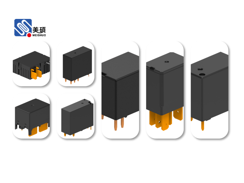
1. Relay: The relay is the central component of the diagram. It consists of a coil, a set of contacts, and a magnetic mechanism. When the coil is energized, the magnetic mechanism pulls the contacts together, thereby closing the circuit.
2. Control Circuit: The control circuit is responsible for energizing the relay coil. It can be a simple switch, a timer, or a more complex circuit that includes various control elements.
3. Controlled Circuit: The controlled circuit is the circuit that is controlled by the relay. It can be any circuit that requires switching, such as a motor, a light, or a heating element.
4. Contacts: The contacts are the switching elements of the relay. They can be normally open (NO) or normally closed (NC). When the relay is energized, the contacts change state, either closing the circuit or opening it.
5. Power Supply: The power supply provides the electrical energy required to operate the relay. It can be an AC or DC source, depending on the application.
Interpreting a Relay Electrical Diagram
Interpreting a relay electrical diagram requires a basic understanding of electrical symbols and circuit components. Here are some key points to keep in mind:
1. Identify the Relay: Look for the relay symbol, which typically consists of a rectangle with a coil and contacts inside.
2. Understand the Control Circuit: Determine how the relay is being controlled. Is it a simple switch, or is there a more complex control circuit involved?
3. Analyze the Controlled Circuit: Identify the components that are being controlled by the relay. This will help you understand the purpose of the relay in the circuit.
4. Note the Contacts: Pay attention to the state of the contacts (NO or NC) and how they change when the relay is energized.
Applications of Relay Electrical Diagrams
Relay electrical diagrams are used in a wide range of applications, including:
1. Industrial Automation: Relay circuits are widely used in industrial automation to control machinery and processes.
2. Home Automation: Relay circuits are also used in home automation to control lighting, heating, and other home appliances.
3. Electrical Distribution: Relay circuits are used in electrical distribution systems to protect against overcurrent and other faults.
4. Telecommunications: Relay circuits are used in telecommunications to switch calls and route signals.
Conclusion
In conclusion, the relay electrical diagram is a vital tool for electrical engineers and technicians. By understanding the components and interpreting the diagrams, you can design and troubleshoot relay circuits more effectively. Whether you are working on industrial automation, home automation, or any other electrical system, a solid understanding of relay electrical diagrams will serve you well.

 Chat Oline