


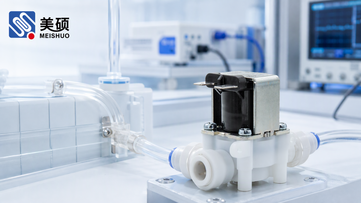
 Smart appliance solenoid valve selection starts before the component shortlist
Smart appliance solenoid valve selection should begin with the finished appliance function, not with a catalogue image. A water valve is the physical actuator in a larger control loop. It receives a command, manages a fluid path and must respond predictably when the appliance changes state or detects an abnormal condition.
For a washing machine, dishwasher, water dispenser or connected water-control product, the right selection depends on more than whether the valve fits the available space. The engineering team must connect the control signal, water path, mating tube, mounting method, environmental conditions and leak-response strategy. If one of these elements is overlooked, a component that looks suitable on paper may create commissioning problems or field-service risk.
This guide provides six practical checks for OEMs and sourcing teams before approving a water-control design. Exact electrical, flow and pressure limits must always be confirmed against the current product documentation and the customer’s test conditions.
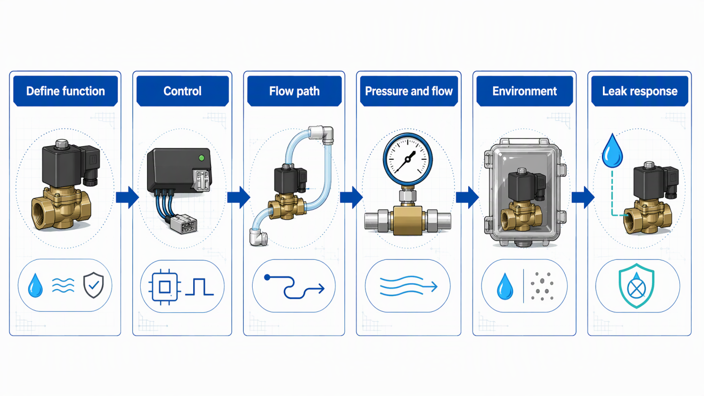
Smart appliance solenoid valve selection decision map
First describe the valve’s role in plain operating terms. Does it admit water during a fill stage, isolate a branch, control a repeatable dosing sequence or support an automatic shut-off response? Identify when the valve is commanded to open, when it must close and what the appliance should do if the expected state is not reached.
This sequence matters because a valve is not selected in isolation from the controller. The appliance may use sensors to confirm water level, flow or moisture. The controller may repeat a command, stop the cycle or alert the user. The valve must be suitable for the intended sequence and the system must define a safe response to an abnormal state.
A clear operating description also helps sourcing teams compare alternatives without relying on vague phrases such as “for smart appliances.”
Confirm the control conditions from the appliance design and current technical documentation. Review the applicable coil or input type, control method, connector arrangement, wiring route and expected operating sequence. If the controller uses a specific output architecture, the valve input must be compatible with that architecture.
The connector is part of the system interface. Check its position, locking method, mating component, cable exit direction and available service clearance. A connector that works electrically but is difficult to assemble or inspect can increase production variation and service time.
Do not approve a replacement because its body appears similar. The control interface, wiring and operating sequence must be reviewed together.
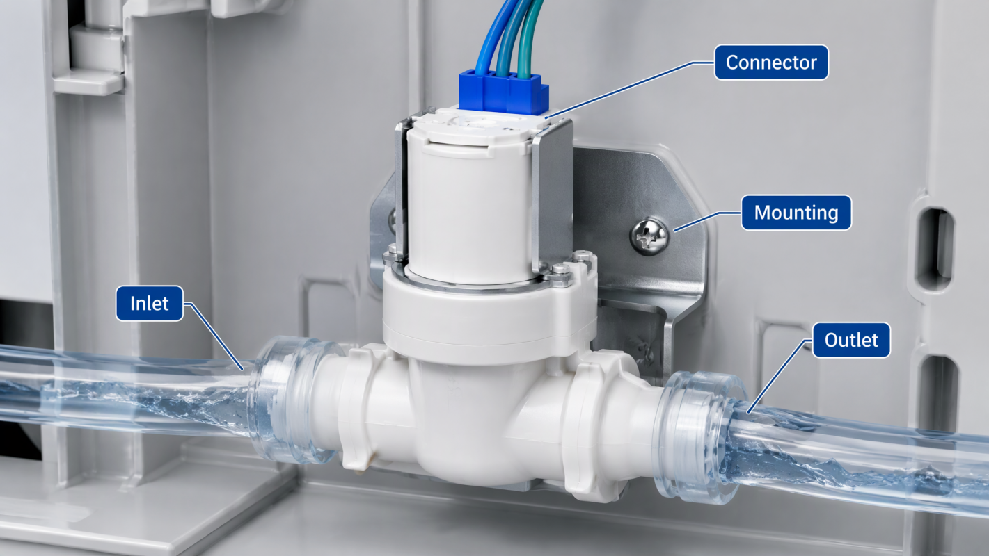 Appliance solenoid valve water path and installation interface
The valve body is only one section of the water path. Review the inlet, outlet, tube material, fitting or push-fit interface, filter arrangement, mounting bracket and nearby components. Confirm that the intended flow direction is compatible with the appliance layout and that the tube route does not place unnecessary force on the valve.
A reliable assembly should be possible without twisting the tubing, stressing the connector or obstructing service access. Consider how the appliance moves during transport, installation and operation. Vibration, repeated handling and nearby components can expose a weak interface even when the valve performs correctly in a bench test.
The design review should also identify where contamination or scale could accumulate and how the relevant area will be inspected or cleaned. The valve should not be expected to compensate for an uncontrolled upstream water path.
Pressure, flow and duty cycle describe different parts of the application. The engineering team should document the expected operating conditions and compare them with the approved valve data. Avoid selecting by one headline number while ignoring the actual tube diameter, upstream condition, downstream restriction, temperature and sequence timing.
The same valve may behave differently in two appliances if the water path, controller timing or installation conditions differ. Testing should therefore use the intended mating parts and a representative sequence rather than a disconnected component alone.
Where the application is still being defined, record the unknowns instead of silently assuming a nominal value. This allows the supplier and OEM to close the technical gaps before release.
Smart appliances can place water-control components near heat sources, moving structures, electronics, insulation or areas exposed to condensation. Review the actual installation environment, cabinet space, orientation, vibration and service conditions. Then confirm that the selected product and assembly process are suitable for those conditions according to current documentation.
Assembly consistency is equally important. Define how the valve is mounted, how the tube is inserted or secured, how the connector is routed and what visual or functional checks are required. A design that depends on a delicate manual adjustment may be difficult to scale across production lines.
For global appliance programmes, document the interface in a way that can be used by engineering, manufacturing, quality and service teams. Consistent terminology reduces mistakes when the product moves between sites or suppliers.
A connected water-control system should explain what happens when the appliance detects unexpected moisture, irregular flow or an incomplete shut-off. EPA WaterSense notes that leak-detection and flow-monitoring devices can identify unexpected dampness or irregular water-use patterns, and that some systems can activate a shut-off valve to reduce water waste and damage.
That principle is useful for appliance design: detection and physical action should be reviewed together. A moisture sensor cannot replace a suitable valve, and a valve cannot decide how the controller should respond. The system should define the signal path from detection to decision to shut-off, as well as the user alert and service procedure.
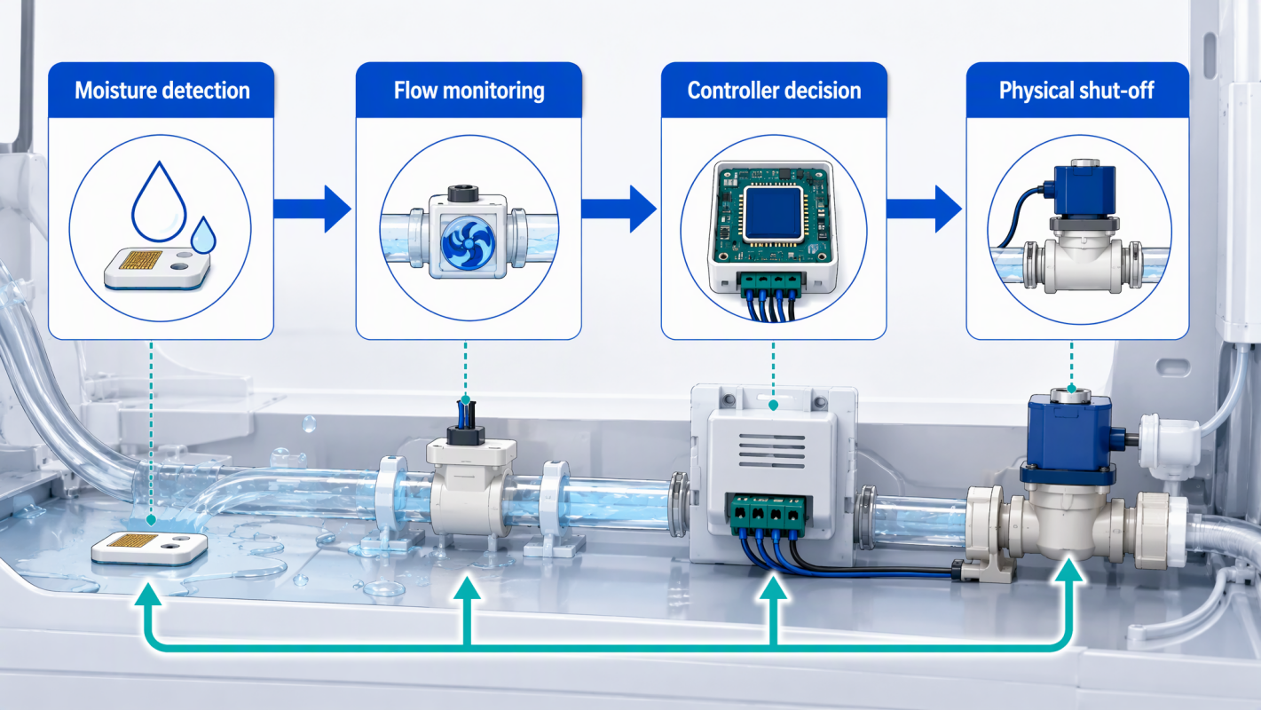
Connected appliance solenoid valve leak response and shut-off architecture
Ask these questions before approval:
• What condition triggers the protective response?
• Does the controller stop the fill command?
• Does the valve close under the defined fault condition?
• How is the user or service team informed?
• Can the appliance recover safely after the event?
• Which parts of the water-control loop are inspected during service?
These questions turn “smart” functionality into a testable engineering requirement.
Component-level checks are useful, but the final validation should use the actual controller, connector, tubing, fittings, mounting method and representative water path. Exercise the normal fill sequence, repeated operation, shut-off and defined abnormal responses. Record what is observed and connect the result to the approved design revision.
Validation should also consider production and service. Can an operator identify the correct orientation? Can a technician replace the valve without damaging the tube or connector? Can the quality team distinguish a valve issue from a system-control issue? A design that performs well but is difficult to assemble or diagnose may still create avoidable cost.
Smart-home technology is moving toward more connected monitoring, remote diagnostics and systems that anticipate or self-correct. That direction increases the value of a dependable physical water-control layer. Connectivity can improve visibility, but the valve, sensor, controller and shut-off path still need clear responsibilities.
Meishuo can support application discussions for water-control components used in connected appliances. Final selection must be confirmed against current technical documentation, mating parts, environmental conditions and application-specific testing.
Define the valve’s role in the complete appliance cycle, including the open command, close command, sensor feedback and response to an abnormal condition.
No. Electrical control, flow path, pressure, connector, mounting, environment and service requirements must also be reviewed.
The mating parts determine mechanical stress, sealing behaviour, flow restriction and assembly consistency. A valve that works alone may not perform the same way in the finished water path.
A sensor can detect moisture or an unusual flow pattern, while the controller interprets the signal and commands a physical shut-off response. The complete chain must be designed and validated together.
Yes. Sharing the control conditions, water path, mating parts, installation environment, duty sequence and validation requirements enables a more reliable technical review.
• External reference: EPA WaterSense — Leak Detection and Flow Monitoring Devices
• External reference: EPA WaterSense — Home Maintenance
• External context: Contractor Magazine — Integrating Smart Home Tech and Hydronic Heating Solutions in 2026

 Chat Oline